
When Single Phase Supply Voltage is 220V, Why is Three Phase 440V and Not 660V?
In an alternator, three separate winding coils are placed around the rotor at 120° angles from each other. Because of this spacing, the electromotive force (EMF) generated in each coil is out of step, or 120° out of phase, with the others. When these three alternating voltages are combined, the result is a three-phase supply system. In contrast, a single-phase system has only one coil, producing a single alternating voltage measured between Phase and Neutral.

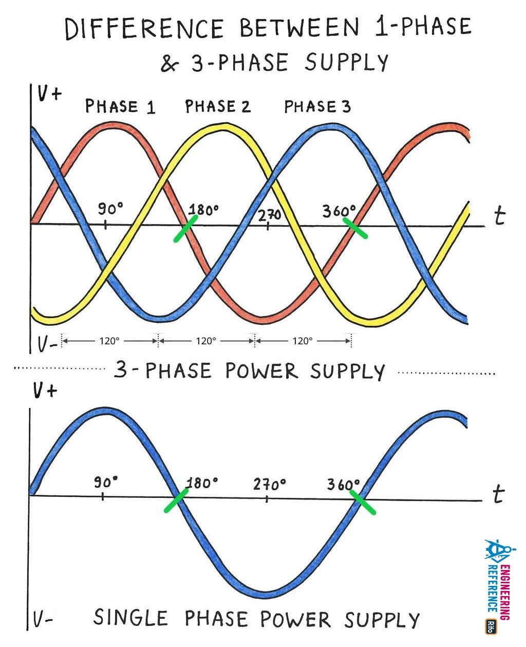
There are 360° in one complete AC cycle. In a three-phase system, this total is divided equally among the three phases—360° ÷ 3 = 120°—so each phase lags or leads the next by 120°. This arrangement ensures a constant power flow and smoother operation of motors and equipment. Imagine three people taking turns to push a swing one after another; the swing never stops because their pushes are evenly spaced—this is similar to how the three-phase voltage waves maintain continuous energy transfer.
On the other hand, a single-phase supply produces only one sinusoidal waveform, completing its entire 360° in each cycle. This means its power fluctuates between zero and maximum twice every cycle, unlike the steady power in a three-phase system.

Voltage in Single Phase Supply System
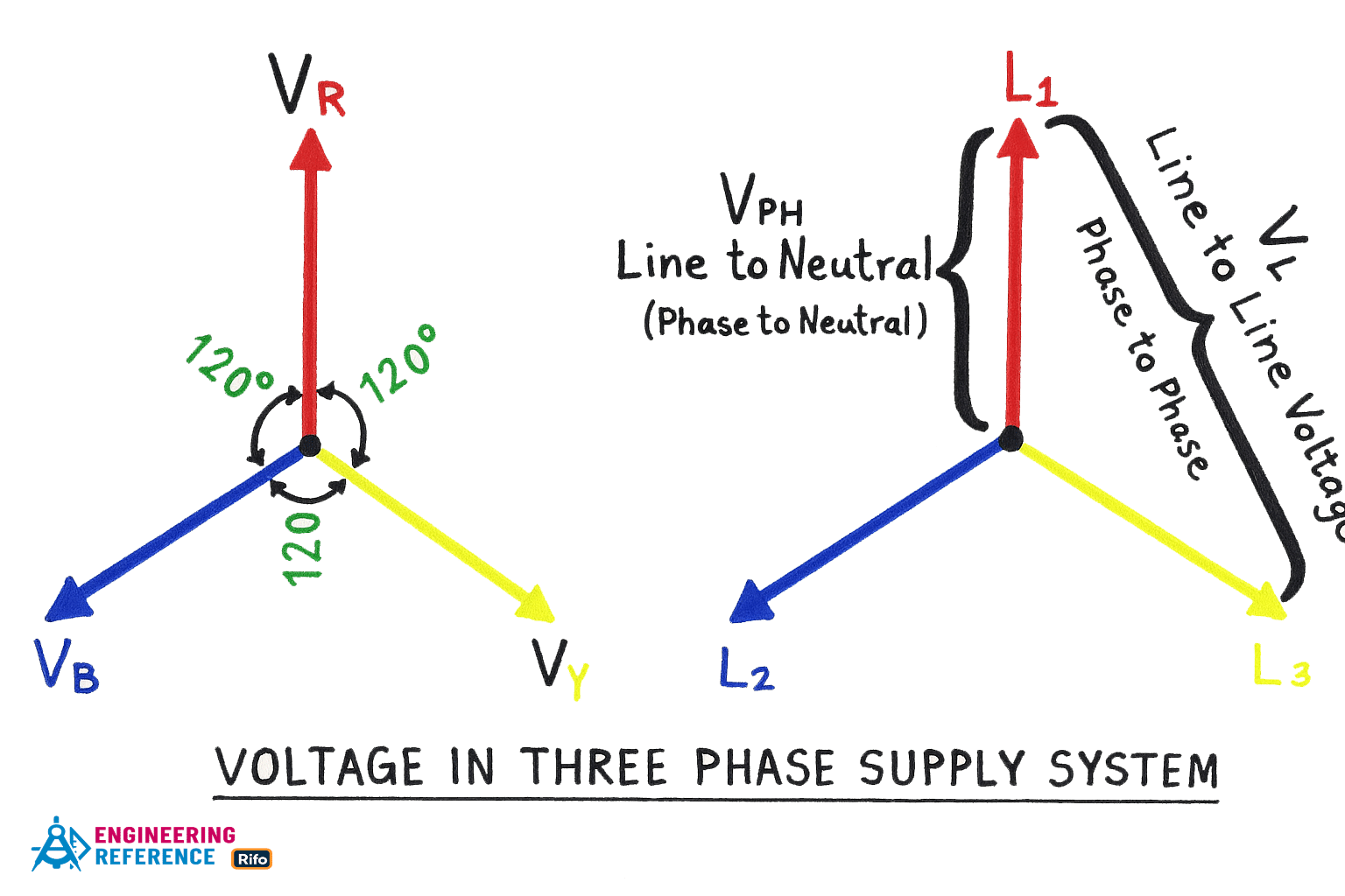
In a single-phase supply system, the voltage measured between the Phase and Neutral is called the Phase Voltage (VPH). The standard value of this voltage is 230V in most countries.
Single Phase Voltage = 230V (Phase to Neutral)
In a three-phase system, each phase is related to the line voltage through the following formula:
Phase Voltage (VPH) = Line Voltage ÷ √3
= 400V ÷ √3 ≈ 230V
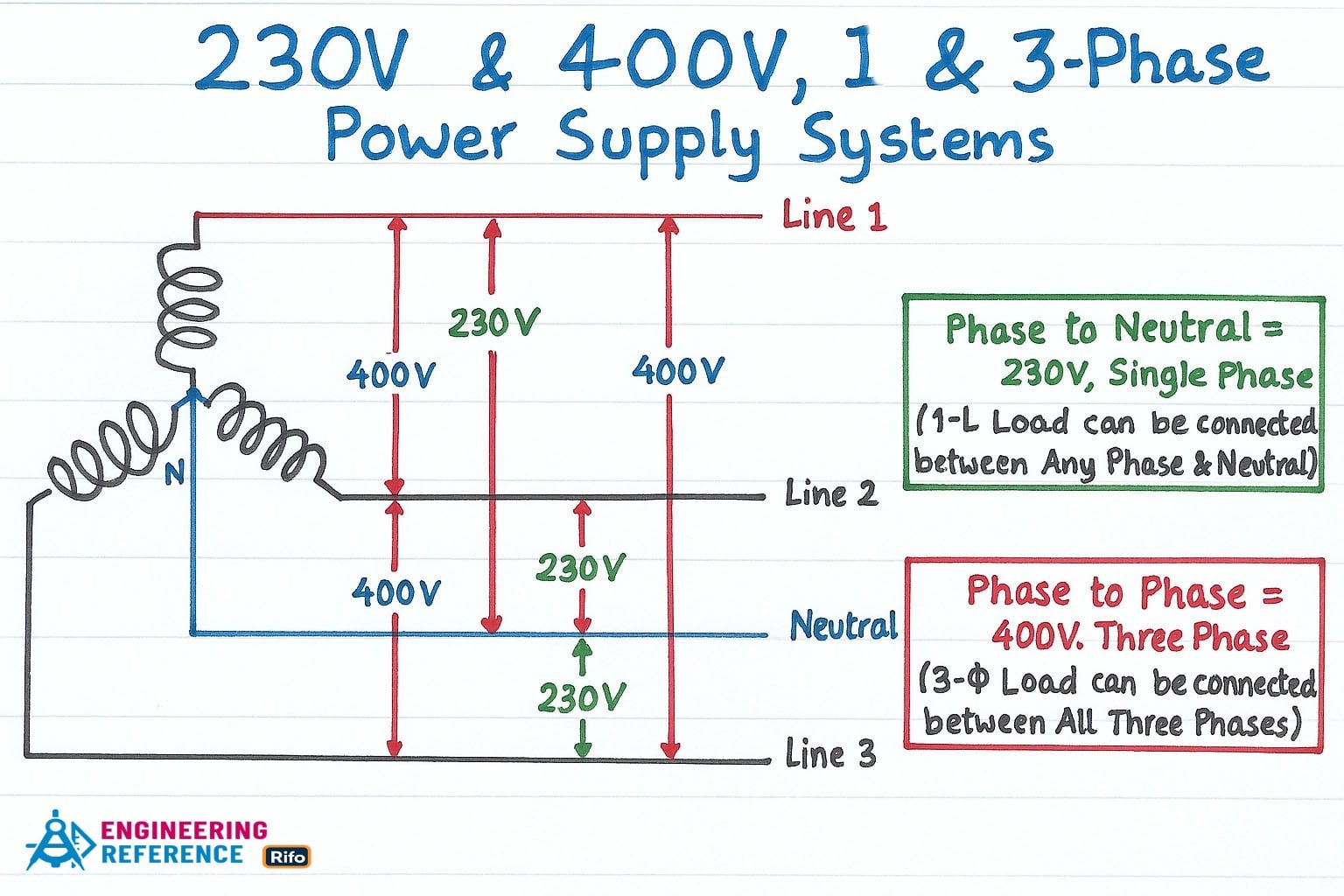
This means that even though the line voltage in a three-phase system is 400V, the voltage between any phase and neutral remains 230V. In simple terms, if you think of three lamps connected to each phase, each lamp receives 230V, just like in a normal household supply, even though the system as a whole operates at a higher combined voltage of 400V.
Read More : Why is a Power Plant Capacity Rated in MW and not in MVA?
Voltage in a Three Phase Supply System
In a three-phase supply system, the voltage measured between any two lines (or phases) is called the Line Voltage (VL). The standard value in many regions is 400V (Line to Line or Phase to Phase).
Three Phase Voltage = 400V (Line to Line or Phase to Phase)
Line Voltage (VL) = √3 × Phase Voltage (VPH)
= √3 × 230V = 398V ≈ 400V
This shows that the line voltage is higher than the phase voltage by a factor of √3. You can imagine each phase as a separate wave spaced 120° apart; when two of these waves are compared, their combined potential difference creates a higher line-to-line voltage.

Note: The voltage between two lines or phases is known as the Line Voltage (VL).
Now, let’s look at how these values differ around the world. The above calculations are based on supply systems used in the UK, EU, and many other countries, where the single-phase voltage is 230V and the frequency is 50Hz. In North America (the US and Canada), systems commonly operate at 60Hz, with various combinations such as 120V, 208V (High Leg Delta), 240V, 277V, and 480V. Similarly, the three-phase voltage in the UK and EU is typically 400V at 50Hz, while in the US and Canada it is 208V, 240V, or 480V at 60Hz.
Some countries follow slightly modified versions of the EU and UK standards. For example, in several Asian countries like India and Pakistan, the single-phase voltage is usually 220V, and the three-phase voltage ranges between 415V and 440V. These small variations depend on national grid configurations, equipment standards, and historical design choices.

Learn more about : Why are Air-Conditioners (AC) Rated in Tons, Not in kW or kVA?
If the Single Phase Supply Voltage is 220V, Why is Three Phase 440V and Not 660V?
This question often causes confusion because it seems logical at first glance—but it’s actually based on a wrong assumption. That’s why the correct comparison should be 230V Single Phase and 400V Three Phase, not 220V and 660V. Let’s break it down in a simple, technical way so that anyone can understand the reasoning behind it.
When people think about a 230V single-phase supply, they sometimes assume that a three-phase supply should just be three times that value, as if you could simply add them together:
= 230V + 230V + 230V = 690V
However, this method doesn’t apply to a three-phase system. The electromotive forces (EMFs) produced in a three-phase alternator are not ordinary numbers that can be added directly—they are vector quantities (or more precisely, phasors) that have both magnitude and direction. Each phase is separated by 120°, so their voltages interact differently.

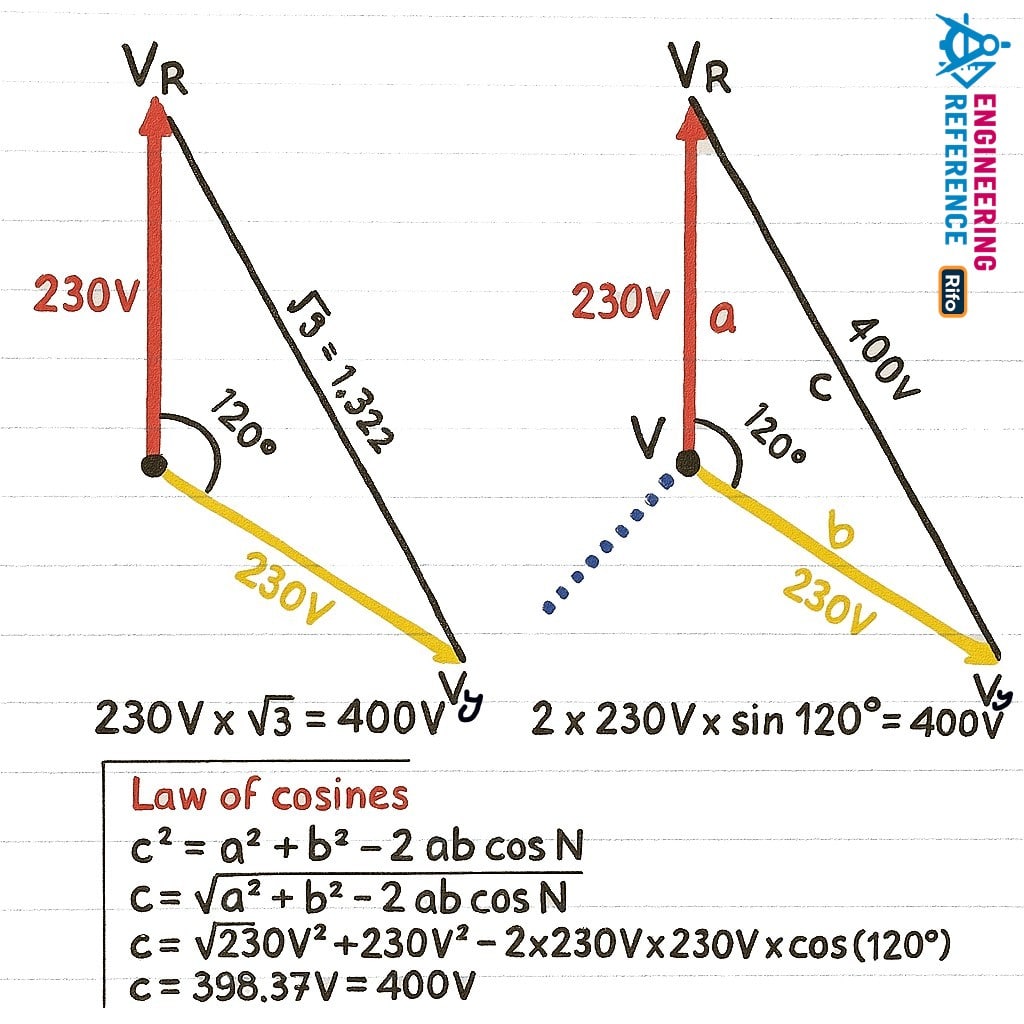
For example, if you take the vector difference between two 230V phase voltages, the result is 400V, not 460V or 690V. This happens because of the 120° phase separation between them, which can be visualized on a phasor diagram. The voltages form an equilateral triangle where the line-to-line voltage equals √3 times the phase voltage.
In short, phasor quantities cannot be added like simple arithmetic values in Kirchhoff’s Current Law (KCL) or Kirchhoff’s Voltage Law (KVL), which apply to instantaneous voltages, not RMS or average values. That’s why a 220V single-phase supply corresponds to about 440V in a three-phase system, and not 660V.

In a three-phase (3-ϕ) supply system, each line carries a voltage of 230V, but because these voltages are 120° apart, their vector difference is nearly 400V between any two phases — whether between Phase 1 and Phase 2, Phase 2 and Phase 3, or Phase 3 and Phase 1. This difference occurs due to the phase angle separating the three alternating voltages. Each phase continually changes direction with time; for instance, at 50Hz, the sine wave reverses direction 50 times per second, completing one full cycle each time.
To calculate the line-to-line voltage, we use the Law of Cosines, a fundamental rule in trigonometry. This law helps find the voltage difference between any two phase vectors that are 120° apart. It explains why the three-phase voltage equals 400V, not 660V or 690V. This principle applies only when there are three separate conductors, each spaced 120° apart in phase.
Explore engineering concepts in : When and Why Did the U.S. Transition from 110V to 120V Supply?
Law of Cosines:
c² = a² + b² – 2ab cos N
c = √(a² + b² – 2ab cos N)
Now, substituting the actual values:
= √[230² + 230² – 2 × 230 × 230 × cos(120°)]
= 398.37V ≈ 400V
This shows that even though each phase has 230V, the vector combination between any two phases results in approximately 400V line voltage—a direct outcome of the 120° phase displacement.

From another perspective, if we plot the sinusoidal waves of a three-phase power system, we can clearly see that each phase is 120° apart from the others. At any given moment, only two phases are positive (+Ve), while the third phase is negative (-Ve). Because the voltages continuously change direction over time, we only consider the two phases that are positive at the same instant. For example, when Phase 1 and Phase 2 are positive, Phase 3 will be negative—and this pattern keeps shifting throughout each cycle.
This is why the voltage difference between any two active phases equals about 400V, not 600V, 660V, or 690V. The value results from the phase displacement of 120° between the lines.
For instance, if the phase voltage between VR and VY is 230V, the phase difference can be calculated as:
2 × 230V × sin(120°) ≈ 400V
This confirms that the effective line-to-line voltage in a three-phase system is around 400V when each phase is 230V.
We can also express the relationship between single-phase and three-phase voltages using simple formulas:
Single Phase to Three Phase:
VPH × √3 = VL
230V × 1.732 ≈ 400V (3ϕ)
Three Phase to Single Phase:
VL ÷ √3 = VPH
400V ÷ 1.732 = 230V (1ϕ)
Where √3 = 1.732
Concluded Points
-
In a Single Phase system, the voltage between Phase and Neutral is 230V.
-
In a Three Phase system, the voltage between any two phases is 400V, not 415V, 440V, 660V, or 690V.
-
Small variations may occur due to permissible limits, for example: 400V ±10% = 440V maximum.
These relationships describe voltage only. When it comes to power, the calculation follows a different principle, which will be explained next.
Check out our guide on : Why 3-Phase Power? Why Not 6, 12 or More for Power Transmission?
If a 1-Phase Power is 230W, Will a 3-Phase Power be 400W or 690W?
Unlike voltage, which is determined by vector relationships, power in an electrical system is additive—it can be added up directly. In a three-phase system, the total power is the sum of the power in each of the three lines.
Power in Single Phase Supply

P = V × I
Where:
P = Power in watts
V = Voltage
I = Current
Power in Three Phase Supply

P = √3 × VL × IL × CosФ
or
P = 3 × VPH × IPH × CosФ
Where:
P = Power in watts
VL = Line voltage
IL = Line current
VPH = Phase voltage
IPH = Phase current
CosФ = Power factor
This formula shows that total three-phase power equals the combined output from all three lines: PR + PY + PB. In other words, if each single phase produces 230W, then the total three-phase power is:
3 × 230W = 690W
This makes it clear that power adds up like ordinary numbers, not like vector quantities such as voltage.
Now that we’ve covered the basics, it should be clear why the voltage between the three lines of a power supply is 400V, not 440V, 460V, or 490V—and how power in a three-phase circuit is calculated differently from voltage.


